Copyright © Chengdu Mini-Microwave Technology Co., Ltd. All Rights Reserved. Site Map
- +86-18180953121+86-15008407113
- 277434684@qq.com
- No. 68, Haichang Road, Huayang Street, Tianfu New District, Chengdu


1.Overview
This product is a special customized part according to the user's needs, and is designed according to the user's index requirements and relevant industry standards.As the basis for product development.
2.Equipment requirements
2.1Performance requirements
a)Operating frequency: 100MHz-3GHz.
b)Frequency resolution: 0.1MHz.
c)Frequency stability: ≤ 1 × 10⁻⁶/24h.
d)Frequency conversion: ≤ 50ms.
e)Full-band output power range: -60dBm ~ + 12dBm.
f)Power accuracy: ≤ ± 1.0 dB.
g)Harmonic suppression: ≥ 20dBc.
h)Clutter suppression: ≥ 50dBc.
i)Built-in battery, continuous working time ≥ 8 H.
2.2Functional requirements
a)Have the function of continuous wave signal generation.
b)With human-machine interface, usually placed on the rack (as armor).
2.3Interface requirements
a)RF output interface (1): SMA-K.
b)DC charging port: TYPE-C interface.
2.4Structural requirements
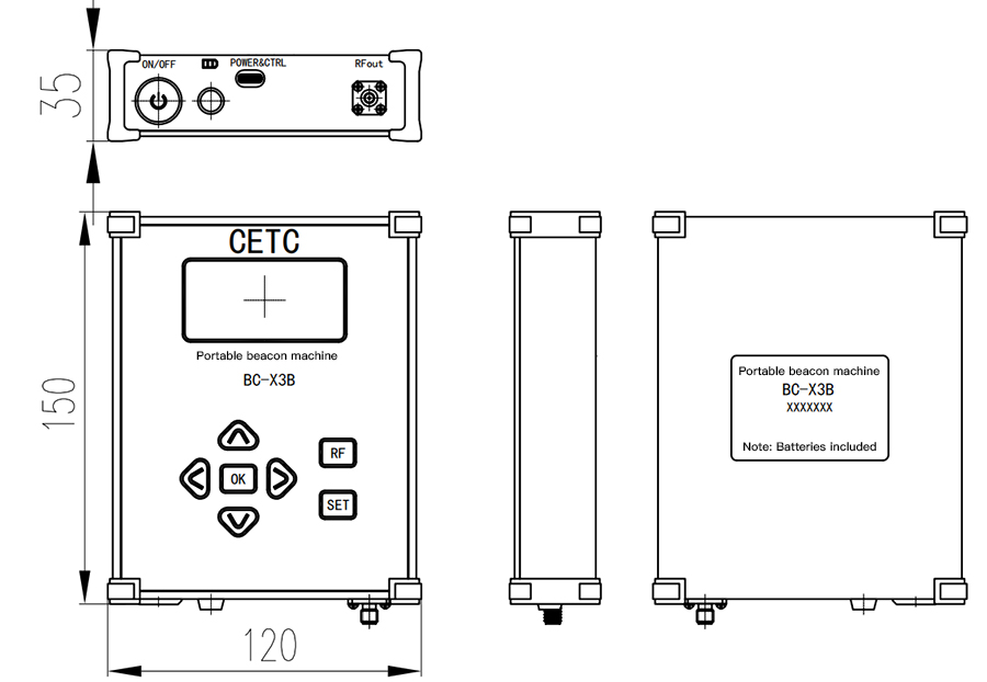
a)Design switch and power indicator (green), volume ≤ 150 mm × 120 mm × 35mm space.
b)The surface is sprayed with powder after being guided, and the color is black matte.
The silk-screen printing shall be carried out according to the contents negotiated by both parties, and the structural design shall meet the structural specification requirements provided by Party A.
3.Design scheme
3.1Composition and function
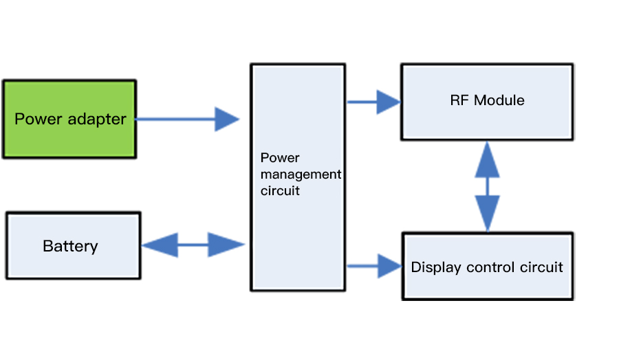
As shown in the figure above, the product is composed of power adapter, battery, power management circuit, RF module and display control circuit.
The power adapter is used to realize AC-DC conversion and supply power for the product.
The battery has the function of charging and reusing, and can supply power for the product when there is no external power supply.
The power management circuit can realize battery charging and discharging management and internal voltage conversion, and provide stable voltage for the internal circuit of the product.
The module is used to generate 100MHz-3GHz RF signals.
The display and control module can realize RF signal frequency control, amplitude control, RF output switch control and battery power detection.At the same time, the working status of the product can be displayed.
3.2How it works
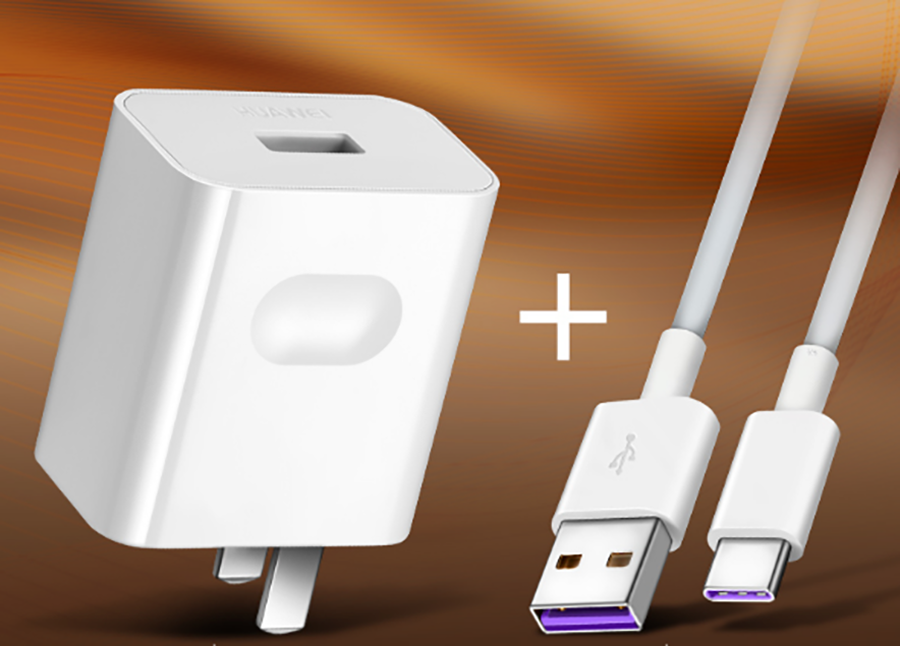
3.2.1Power adapter
The TYPE-C interface standard 5V2A charger produced by Huawei is adopted, and the input voltage is 100 ~ 240V 50/60Hz. The appearance of the product is shown in the figure below.
3.2.2Battery
The appearance and main technical parameters of the lithium battery with flexible package are as follows.
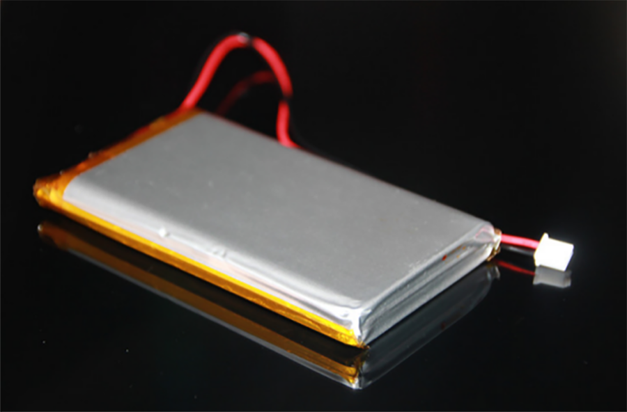
The main technical parameters of the battery are as follows:
1)Nominal battery voltage 3.7 V, battery capacity 10 Ah
2)Good safety, with overcharge protection, overdischarge protection, overcurrent protection
3)Technical parameters of protection IC: overcharge protection voltage 4.20 V ± 0.05 V
4)Over-discharge protection voltage 2.7 V ± 0.1 V
5)Overcurrent protection 3.0 ± 1.0 A (2.7 V ~ 4.25 V)
6)Discharge temperature: -20 ° C ~ + 60 ° C
7)Charging temperature: 0 ° C ~ + 50 ° C
8)The overall dimensions are 112 × 66 × 11 and the weight is 100g.
9)After 1000 times of continuous charge and discharge, the battery capacity shall not be less than 80% of the rated capacity.
3.2.3 Power management circuit
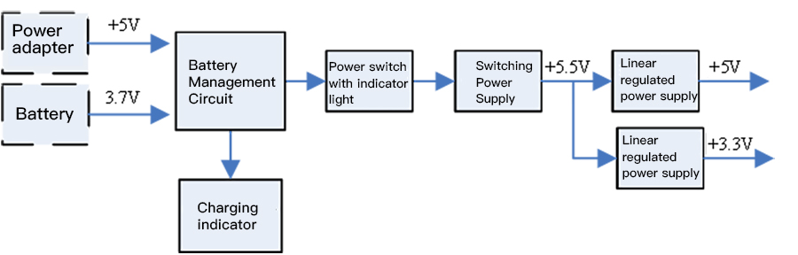
As shown in the figure above,The power supply management circuit consists of a charging and discharging management and electric quantity detection circuit, a charging indicator light, a power supply switch, a power supply indicator light, a switching power supply,Linear regulated power supply.
The power management circuit can realize the charging and discharging management of the battery,It is used to provide the input DC 5V to the load and judge whether it is in pre-charging, constant current charging, constant voltage charging or stop charging according to the voltage of the lithium battery.At the same time, the dual redundancy design of hardware and software is adopted to ensure that the lithium battery will not overcharge, overdischarge, overtemperature and overcurrent.
The charging indicator is red and green, the charging status is red, and the charging completion is green.
Power switch (with lamp) can realize on-off control of power supply and power-on indication.
Switching power supply and linear regulated power supply can realize voltage conversion and provide stable power supply for the internal circuit of the product.
3.2.4 Display and control circuit
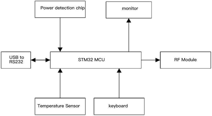
As shown in the figure above, the control circuit uses STM32 MCU as the controller.One RS232 interface is directly connected to the USB interface of the computer through the TYPE-C interface after being converted from the USB interface to the RS232 interface to realize the communication between the module and the computerA temperature sensor is arranged on the surface of the battery to carry out over-temperature protection on the battery,Receiving a control instruction input by the keyboard to control the working state of the radio frequency module and the display update of the OLED display,The OLED display uses a 2.4-inch display with a resolution of 128 X 64 dots.The display is used to display parameters such as frequency, power, output status and battery capacity (see the product outline drawing for the appearance of keyboard and display).
3.2.5 RF module
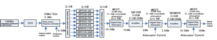
As shown in the figure above,The RF module is composed of TCXO, DDS, PLL frequency synthesizer, switch, filter, digital step attenuator and amplifierCheng.
The temperature compensation crystal oscillator is used for generating a reference signal.
The DDS is used to generate a variable reference signal.
Phase-locked frequency synthesizer is used for product RF signal.
Switches and filters form a one-of-eight switching filter bank, which can improve the harmonic suppression of output signals.
The digital step attenuator is used for debugging the amplitude of the output signal.
The amplifier is used for amplifying the output signal.
4.Overall dimensions of the product